Taking you one step ahead
VPNs and VRFs
Today we have an extremely exciting topic and I'm sure you'll agree. We've had the pleasure of working with a client of ours who had an interesting requirement. This client of ours had several offices around Europe. The sites are obviously interconnected using VPN over the Internet in a redundant way (maybe another article should be describing that). The requirement was for a designated SSID in one office, which can be used to access the internet using another office. The office in question was in Budapest and the requirement was for visitors from the London office to be able to browse the internet as if they were in the UK. This is a nice gesture, as you know, Google is redirecting you to a country-specific subdomain. So visitors were redirected to google.hu (for Hungary) and the search engine was favouring hungarian results for queries. They'd prefer to be redirected to google.co.uk instead and also, some basic traffic accounting is also requried to tell: how much traffic are we talking about. I think our clients could benefit from this solution, so let's see how we did it.
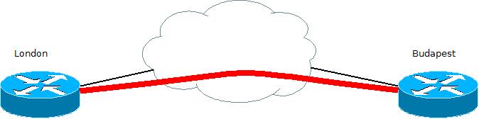
Let's have a step-by-step approach and let's discuss problems as we bump into them, rather than having a paragraph about background, etc. So we're looking at a router that has LAN and WAN connections and also, has a tunnel interface pointing to the other side. There is also a routing protocoll in place, so the two sites can see each other. This is our base, we're building the configuration from here. So obviously we need to create a separate VLAN for roaming clients (let's call visitors like that). Let's see what we have so far:
interface Dialer0 description [wan] pppoe ip address negotiated ip access-group acl_outside-in-v4 in ip mtu 1492 ip nat outside ip virtual-reassembly in encapsulation ppp ip tcp adjust-mss 1452 dialer pool 1 dialer-group 1 keepalive 15 3 ppp authentication chap callin ppp chap hostnameppp chap password 7 ppp ipcp route default crypto map l2l_vpn
The above is a normal ADSL WAN configuration, with NAT enabled, ACL filtering traffic from the internet and having a VPN crypto map applied to it. Let's see the LAN side:
interface Vlan2 description [lan] ip address 192.168.25.238 255.255.255.240 ip nat inside ip virtual-reassembly in load-interval 30 ipv6 addressipv6 nd router-preference High
As you can tell, there is IPv6 enabled on the LAN side, but otherwise it's a simple LAN config. Let's move on to the VPN connection between sites:
The VPN needs an ISAKMP policy:
crypto isakmp policy 20
 encr aes
 authentication pre-share
 group 14
An IPSEC policy with pre-shared keys:
crypto isakmp keyaddress no-xauth crypto ipsec transform-set aes_sha256 esp-aes esp-sha256-hmac
An ACL to define interesting traffic:
ip access-list extended acl_crypto_ken
 permit gre host 172.31.255.126 host 172.31.255.124
 permit icmp host 172.31.255.126 host 172.31.255.124
 permit gre host 172.31.255.123 host 172.31.255.121
 permit icmp host 172.31.255.123 host 172.31.255.121
And we need the crypto map to be configured as well:
crypto map l2l_vpn 30 ipsec-isakmp set peerset transform-set aes_sha256 match address acl_crypto_ken
Now let's look at the crypto ACL. If you've created site-to-site ipsec tunnels before, you are aware that routing doesn't work with that. You need a GRE tunnel across to carry layer 3 protocols, such as routing. So immediately after you've seen the ACL entries, you knew that the loopback interface is missing. Let's have this added as well:
interface Loopback0
 ip address 172.31.255.126 255.255.255.255
There. As our default gateway points towards the internet, no need to add a static route for the remote end's loopback address. Once all the above is configured, the only thing left is the tunnel itself. As you can probably tell: this is the old school method as I'm not using VTIs here.
interface Tunnel11
 description [gre-ipsec lhr-ken]
 ip address 172.31.255.73 255.255.255.252
 keepalive 3 3
 tunnel source Loopback0
 tunnel destination 172.31.255.124
That's done. Connectivity is up and running fine, so let's add routing. I've chosen OSPF:
router ospf 100
 passive-interface default
 no passive-interface Tunnel11
 no passive-interface Vlan2
 network 172.31.255.72 0.0.0.3 area 0
 network 192.168.25.224 0.0.0.15 area 0
The remote end is obviously configured in a similar way, but as we have a lot ahead of us, I won't bore you with the details. Instead, let's look at the routing, so we can get started:
c881-bud.lehel#sh ip route ospf
[...]
O        192.168.25.192/27 [110/1001] via 172.31.255.74, 00:59:34, Tunnel11
From the above output, you can see that the remote network, 192.168.25.192/27 is learned successfully and is reachable for the local LAN, 192.168.25.128/28. So this is where we are, time to get to work.
So let's walk through on what needs to be done, shall we? So a new VLAN has to be created. Of course, this has to be isolated from the existing ones as it's only purpose is to provide internet access. Roaming clients will be placed in to this VLAN (over wired or wireless). From here, apart from being isolated, they need to have a default route that points towards the London site, from where they would get out to the internet.
Let's spend a moment on thinking about isolation. We could use ACLs for blocking traffic from the roaming client vlan towards the production vlan. Then we would have to use policy routing, as we already have a default route that points towards the local internet breakout point. We'd have to use PBR to set a next hop for a certain type of traffic. Not to mention that we'd have a hard time in traffic accounting, when we'd measure how much of the traffic between the sites are roaming client traffic. So we'd have to have a separate tunnel brought up between sites, and that tunnel interface would be dedicated to the roaming client traffic. What if this needs to be expanded and more offices need to have remote breakout points for internet traffic? What if UK traffic needs to leave the network at the UK site, but others need to leave somewhere else? This screams routing, which screams VRFs. It also takes care of the isolation, so this is how it's going to be done.
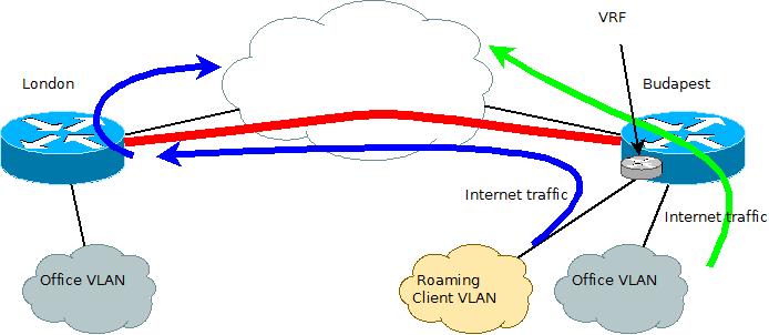
Let's spend a moment on discussing VRFs. VRF stands for Virtual Routing and Forwarding. Essentially a VRF to routing, is what a VLAN is for switching. VRFs are commonly known to be used together with MPLS networks, where customer traffic separation is required. When used without, it is usually referred to as VRF-Lite. This is what we're going to be using today. As mentioned, our primary goal for using VRF is traffic separation. A VRF is basically a separate routing table to the default routing table, which is referred to as a global routing table in VRF terminology. What this means that traffic entering on an interface designated to a VRF does not use the global routing table, but the separate VRF routing table. So what does this mean? It means that a router can have multiple default gateways, one for each VRF. So, in this particular case, we'll use the global routing table's default gateway for local traffic, but will use a VRF for roaming clients, with a default gateway set to the remote site. Let's look at a diagram how this looks like.
Let's see how this is configured on the router in Budapest. Let's start with the VRF and the new VLAN:
ip vrf roamingclient
 description used for tunneling cross-site traffic
 rd 1:1
[...]

interface Vlan6
 description [roaming client lan]
 ip vrf forwarding roamingclient
 ip address 10.8.31.1 255.255.255.224
So now let's see the VRF in action: looking at the global routing table does not show the entry for Vlan 6, but the VRF routing table does:
c881-bud.lehel#sh ip route 10.8.31.1
% Subnet not in table
c881-bud.lehel#sh ip route vrf roamingclient 10.8.31.1
[...]
Routing entry for 10.8.31.1/32
  Known via "connected", distance 0, metric 0 (connected)
  Routing Descriptor Blocks:
  * directly connected, via Vlan6
      Route metric is 0, traffic share count is 1
The next thing is to establish a second GRE tunnel, belonging to the same VRF as Vlan6, this is so traffic can be tunneled separately to the remote site. We could be using the existing tunnel for this, the reason for a second tunnel is purely for separation of traffic, as the existing tunnel carries office vlan traffic between sites.
interface Tunnel30
 description [roaming client gre vrf]
 ip vrf forwarding roamingclient
 ip address 172.31.255.77 255.255.255.252
 ip virtual-reassembly in
 keepalive 3 3
 tunnel source Loopback1
 tunnel destination 172.31.255.121
As this second tunnel is not really interesting from a VRF point of view, we'll skip the steps setting it up. It's identical to the existing one which is already explained above. It's now time to discuss how is traffic handled on the remote end in the London office. To have the traffic kept under close monitoring, a spare firewall was used to have the traffic broken out to the internet. The main idea is to hairpin the route: as traffic comes in through the Tunnel in the relevant VRF, it is then handed off to an external firewall (an ASA5505 in this case) in a dedicated vlan. Then the the traffic will travel through the firewall to a second interface, which is then looped back to the router - now in the global routing table - without VRF. Have a look at the diagram for the third time, where the new items have been drawn for your better understanding.
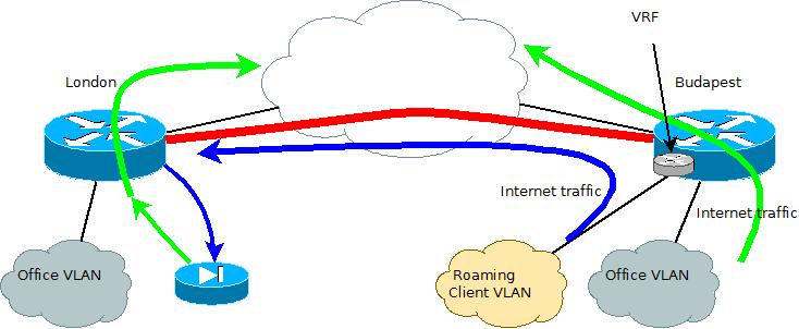
If you look at the colors, the blue lines indicate the traffic while travelling within the VRF. It is represented with a green arrow when exiting the firewall, now in the global routing table, travelling towards the internet. This is our final stage of configuration as we now have achieved our goal. The customer is happy to be able to physically control traffic (at any time, the UTP cable can be disconnected without breaking legitimate traffic), monitor its volume and can introduce additional firewall or inspection rules, if needed. I think this is a pretty good example of introducing VRFs into a non-enterprise network and it shows how small companies can benefit from this technology.